Terminating Cat5e Cable on a Jack
|
 |
This how-to explains how to terminate Cat5, Cat5e cables on a Jack used on wall plates or patch panels. Using this procedure will enable you to produce repeatable good quality terminations with a neat appearance and without breaking any wires. This will save you time and effort as well as the frustration caused by needing to redo the termination.
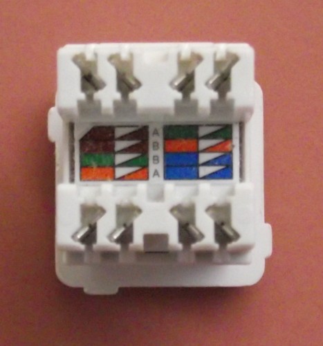
This procedure uses a EIA/TIA 568A termination, shown as row A on the Jack shown in this guide. To use TIA/EIA 565B terminations use row B on the jack and follow it's colour coding (if your jack is not exactly the same use your Jack's colour coding.)
Tools & Cable you will need:
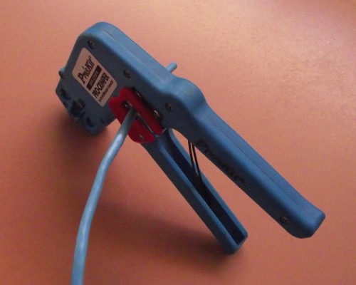
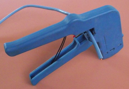
- RJ45 Crimp Tools
For a full range or RJ Crimp Tools see here - Punch Down Tools
For a full range or Punch Down Tools see here - Wire Trimmers/ Cutters /Side Cutters
For a full range or Side Cutters see here - Cat5e and Cat6 Cable
For a full Range of Cat5e Solid, Stranded, Outdoor, Shielded and Cat 6 cables on reels see here
Step 1Place the Jack you are going too use somewhere on a flat surface.
|
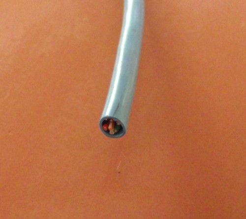
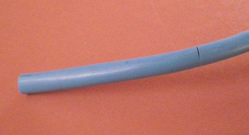
Step 2Trim your cable to give a neat end.
|
Step 3Carefully score or cut the sheath so there will be 50mm to 75mm of wires protruding once the sheath is removed.
|
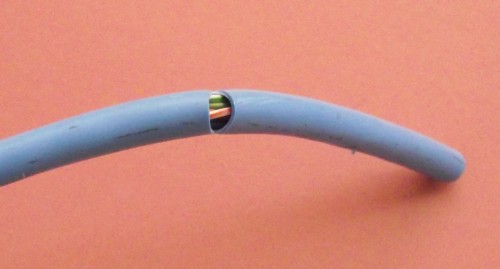
Step 4When scoring/cutting the sheath be careful not to nick any of the pairs as this causes them to break in the punch down process, and is not always visible as the wire coating keeps the wire intact even though broken inside.
|
Step 5There is no need to cut the sheath all the way around, or all the way through. Only cut or score the sheath so the sheath will break away reasonably easily.
|
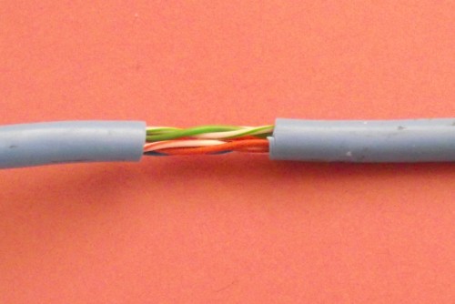
Step 6Bend the sheath to break the cut further.
|
Step 7Pull the sheath away from the break to break the sheath off completely.
|
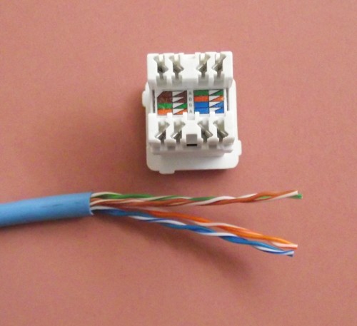
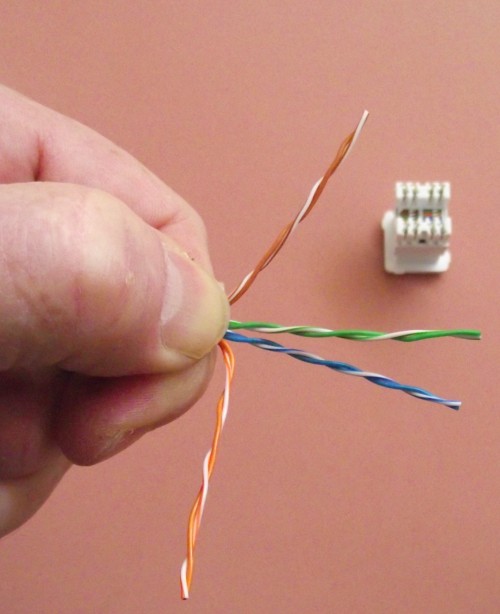
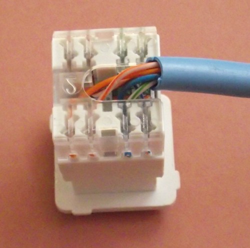
Step 8Turn the cable so the pairs on the correct side and match layout of the jack. The diagram shows Brown & Green pairs at the top with blue and orange at the bottom.
|
Step 9Grip the cable firmly and separate the pairs again to match the jack. Brown, Green at the top blue & orange at the bottom.
|
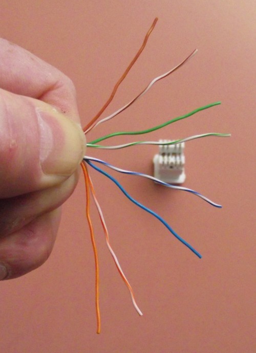
Step 10With the cable still gripped fairly separate out all the pairs to suit the jack.
|
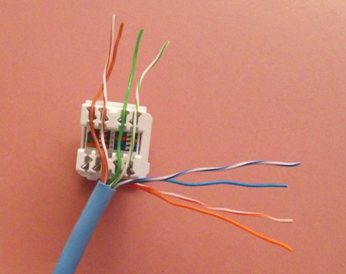
Step 11Place base of the cable (where the sheath ends) on one side of the jack as shown below. Place the wires over the correct slots on the other side of the jack. Placing the wires in this manner ensures that the wires are not so short they do not break when using the punch down tool.
|
Step 12Push the wires into each slot using the punch-down tool. It is not necessary to actually punch the wires down. This actually tends to break the wires near where they enter the slot.
|
Step 13Shown below are the wires pushed into the slots on one side..
|
Step 14Now fold the cable back over the slots fitted with pairs.
|
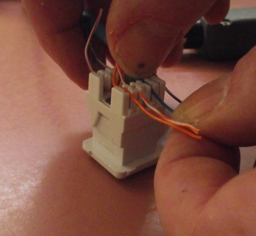
Step 15Place the remaining wires over the correct slots. Use your thumb to push the wires into position.
|
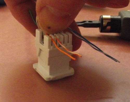
Step 16To get the wires into place push down with your thumb whilst holding the end of the wire with your other hand.
|
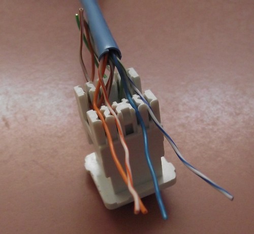
Step 17The wires are shown in the diagram below in position ready for using the punch down tool
|
Step 18After using the punch down tool the wires should look as shown below.
|
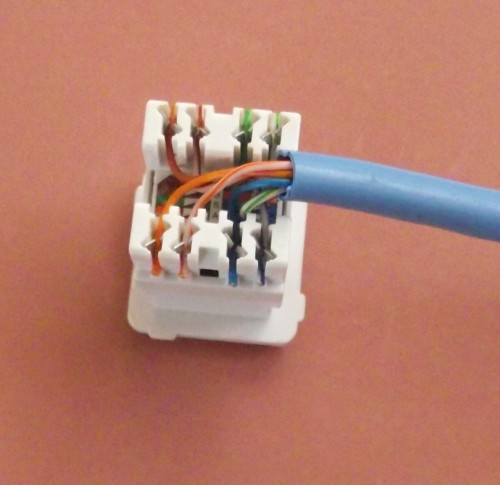
Step 19Trim the excess off each wire.
|
Step 20The Jack with the wires trimmed is shown below. The cable has also been placed into position for fitting the cover.
|
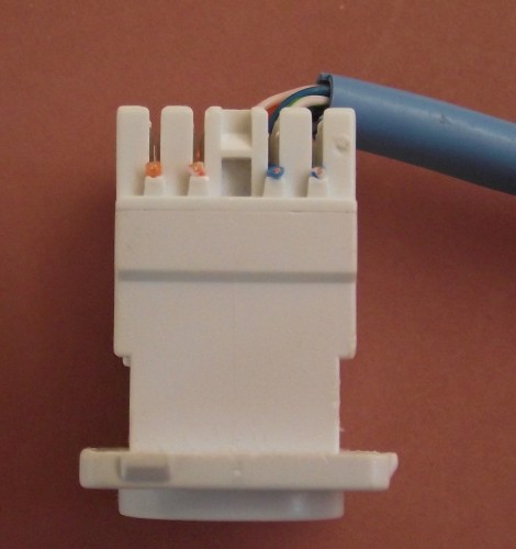
Step 21The Jack with the wires trimmed is from the side.
|
Step 22The Jack is then fitted with a cover as shown below.
|
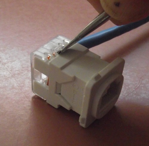
Step 23If the cover is required to be removed it can be removed by placing a small screwdriver as shown below and gently levering. The cover will simply pop off. Trying to remove the cover via levering from other places will result in the cover being damaged.
|


Copyright © InfoComm Engineering 11 June 2011